![]()
![]()
![]()
![]()
![]()
![]()
Connectors
|
Connectors |
|
|
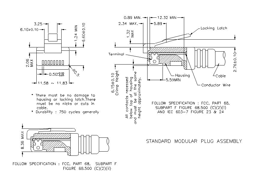
SM000618 10 Base-T 100 Base-T 1000 Base-T 1. MECHANIC DIMENSIONS 1.1. Dimensions 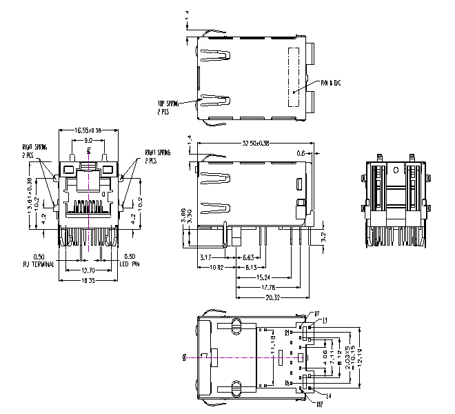
General Tolerance: .X :
±0.25
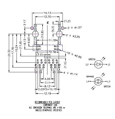
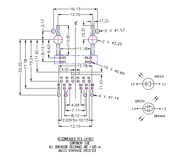
1.2. PCB Layout 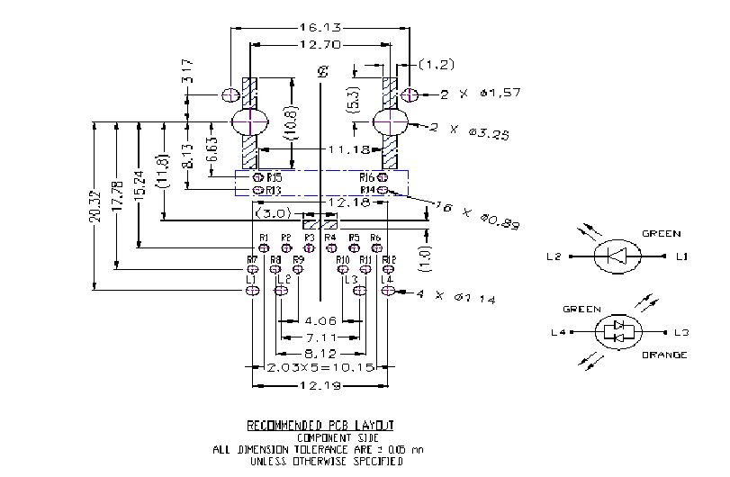
1.3. RJ PLUG SPECIFICATION
2. REQUIREMENTS
2.1 Design and Construction
2.2 Materials 2.2.1 Terminal Parts :
2.2.1.1
RJ Terminal : Phosphor Bronze ,
Thickness=0.30mm
2.2.1.2
Input Terminal : Brass ,
Thickness=0.35mm
2.2.1.3
Module Terminal : Brass ,
Thickness=0.30mm
2.2.2 Plastic Parts :
2.2.2.1
Housing : High temp. Thermoplastic, Black
2.2.2.2
Coil Case : High temp. Thermoplastic, Black
2.2.2.3
Cover : Thermoplastic , PBT , Black
2.2.3 Shell Parts :
2.2.3.1
Shell : Stainless, Thickness=0.20mm
2.3 Operating and Storage Temperature 2.3.1 Operating Temperature : 0℃ TO +70℃ 2.3.2 Storage Temperature : -40℃ TO +85℃
2.4 RJ45 specifications: 2.4.1 Insulation Resistance: 500MΩMin 2.4.2 Dielectric Withstanding Voltage: 1000VAC Min
2.5
Performance and Test Description All tests are performed at ambient environmental conditions per MIL-STD-1344A and EIA-364 unless otherwise specified.
2.6
Packaging and Packing shipment and storage.
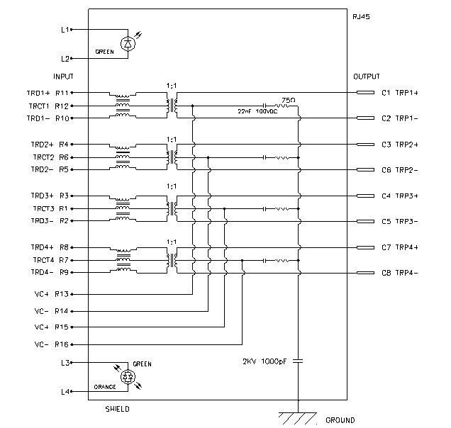
3. ELECTRICAL CHARACTERISTICS 3.1. SCHEMATIC

3.2
Transmitter filter & Receiver filter 80~100 MHz –10dB MIN. load 100Ω
3.3 Common Mode Rejection
3.4 Cross Talk 3.5 INDUCTANCE @ 100KHz, 0.1V, 8mA DC BIAS Input(R11-R10), Input(R4-R5), Input(R3-R2), Input(R8-R9): 350mH MIN. ( @ 100KHz, 0.1V, 8mA DC BIAS) Input(R11-R10), Input(R4-R5), Input(R3-R2), Input(R8-R9): 350mH MIN. ( @ 100KHz, 0.1V, 24mA DC BIAS)
3.6 HiPot TEST
3.7 Balanced DC line current 720mA MAX @57VDC continuous 1.2A MAX @57VDC for 200milliseconds  SM000640 10 Base-T 100 Base-T 1000 Base-T 1. MECHANIC DIMENSIONS 1.1. Dimensions 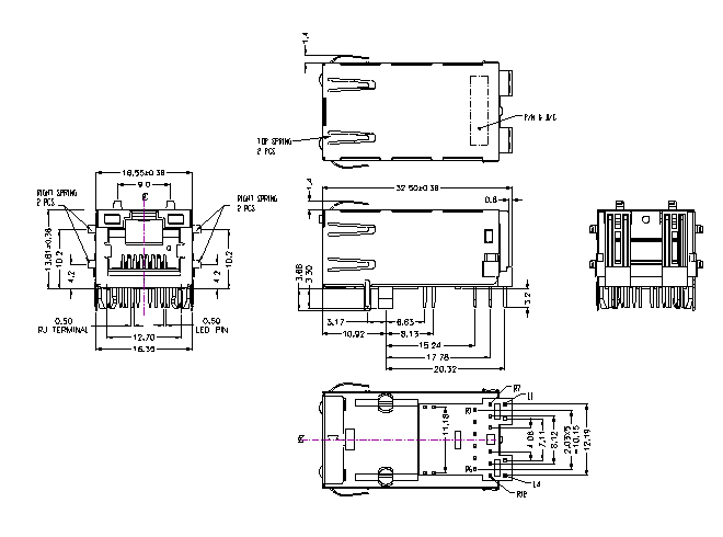
General
Tolerance : .X :
±0.25 1.2. PCB Layout  1.3 RJ PLUG SPECIFICATION 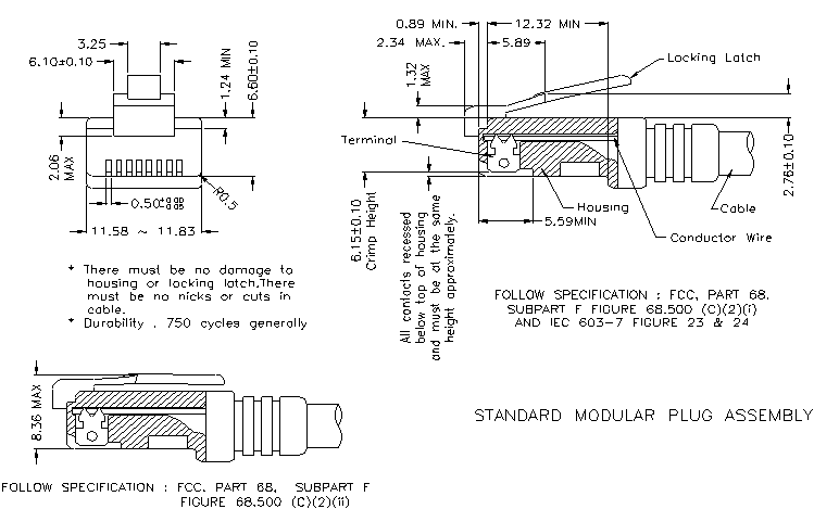
2. REQUIREMENTS
2.1 Design and Construction:
2.2 Materials 2.2.1 Terminal Parts :
2.2.1.1
RJ Terminal : Phosphor Bronze ,
Thickness=0.30mm
2.2.1.2
Input Terminal : Brass ,
Thickness=0.35mm
2.2.1.3
Module Terminal : Brass ,
Thickness=0.30mm 2.2.2 Plastic Parts :
2.2.2.1
Housing : High temp. Thermoplastic, Black
2.2.2.2
Coil Case : High temp. Thermoplastic, Black
2.2.2.3
Cover : Thermoplastic , PBT , Black 2.2.3 Shell Parts :
2.2.3.1
Shell : Stainless, Thickness=0.20mm
2.3 Operating and Storage Temperature 2.3.1 Operating Temperature : 0℃ TO +70℃ 2.3.2 Storage Temperature : -40℃ TO +85℃
2.4 RJ45 specifications: 2.4.1 Insulation Resistance: 500MΩMin 2.4.2 Dielectric Withstanding Voltage: 1000VAC Min
2.5
Performance and Test Description All tests are performed at ambient environmental conditions per MIL-STD-1344A and EIA-364 unless otherwise specified.
2.6
Packaging and Packing shipment and storage.
3. ELECTRICAL CHARACTERISTICS 3.1. SCHEMATIC  3.2.
Transmitter filter & Receiver filter 80~100 MHz –10dB MIN. load 100Ω
3.3 Common Mode Rejection
3.4 Cross Talk 3.5 INDUCTANCE @ 100KHz, 0.1V, 8mA DC BIAS Input(R11-R10), Input(R4-R5), Input(R3-R2), Input(R8-R9): 350mH MIN. ( @ 100KHz, 0.1V, 8mA DC BIAS) Input(R11-R10), Input(R4-R5), Input(R3-R2), Input(R8-R9): 350mH MIN. ( @ 100KHz, 0.1V, 24mA DC BIAS)
3.6 HiPot TEST
3.7 Balanced DC line current 720mA MAX @57VDC continuous 1.2A MAX @57VDC for 200milliseconds
 SM000650 10 Base-T 100 Base-T 1000 Base-T RJ-45 for PoE 1. MECHANIC DIMENSIONS 1.1. Dimensions 
1.2. PCB Layout
1.3. RJ PLUG SPECIFICATION
2. REQUIREMENTS
2.1 Design and Construction
2.2 Materials 2.2.1 Terminal Parts :
2.2.1.1
RJ Terminal : Phosphor Bronze ,
Thickness=0.30mm
2.2.1.2
Input Terminal : Brass ,
Thickness=0.35mm
2.2.1.3
Module Terminal : Brass ,
Thickness=0.30mm 2.2.2 Plastic Parts :
2.2.2.1
Housing : High temp. Thermoplastic, Black
2.2.2.2
Coil Case : High temp. Thermoplastic, Black
2.2.2.3
Cover : Thermoplastic , PBT , Black 2.2.3 Shell Parts :
2.2.3.1
Shell : Stainless, Thickness=0.20mm
2.3 Operating and Storage Temperature 2.3.1 Operating Temperature : -40℃ TO +85℃ 2.3.2 Storage Temperature : -40℃ TO +85℃
2.4 RJ45 specifications: 2.4.1 Insulation Resistance: 500MΩMin 2.4.2 Dielectric Withstanding Voltage: 1000VAC Min
2.5
Performance and Test Description All tests are performed at ambient environmental conditions per MIL-STD-1344A and EIA-364 unless otherwise specified.
2.6
Packaging and Packing during shipment and storage.
3. ELECTRICAL CHARACTERISTICS 3.1. SCHEMATIC
3.2
Transmitter filter & Receiver filter 80~100 MHz –10dB MIN. load 100Ω
3.3 Common Mode Rejection
3.4 Cross Talk
3.5 INDUCTANCE @ 100KHz, 0.1V, 8mA DC BIAS
3.6 HiPot TEST
Input(R3-R2) to
Output(C4-C5) : 1500VAC, 60sec or 2250VDC, 60sec
SM000651 10 Base-T 100 Base-T 1000 Base-T RJ-45 for PoE + 1. MECHANIC DIMENSIONS 1.1. Dimensions 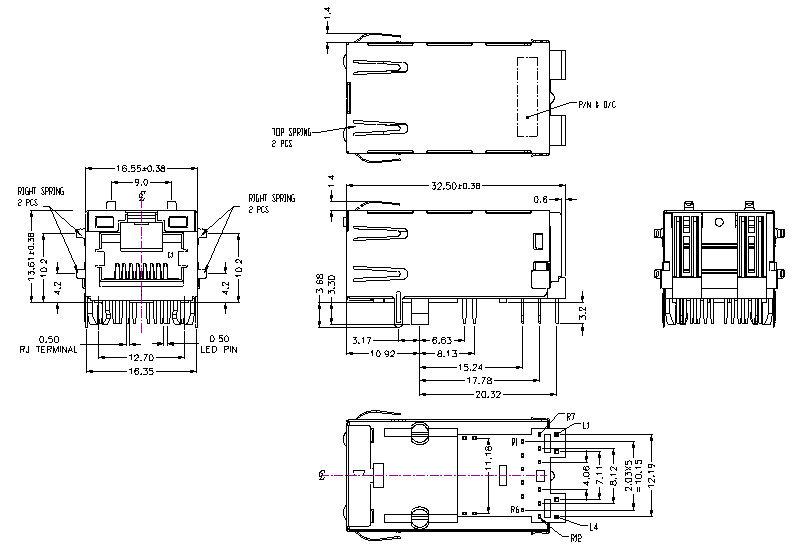
General Tolerance: .X :
±0.25 1.2. PCB Layout
1.3. RJ PLUG SPECIFICATION 
2. REQUIREMENTS
2.1 Design and Construction
2.2 Materials 2.2.1 Terminal Parts :
2.2.1.1
RJ Terminal : Phosphor Bronze ,
Thickness=0.30mm
2.2.1.2
Input Terminal : Brass ,
Thickness=0.35mm
2.2.1.3
Module Terminal : Brass ,
Thickness=0.30mm
2.2.2 Plastic Parts :
2.2.2.1
Housing : High temp. Thermoplastic, Black
2.2.2.2
Coil Case : High temp. Thermoplastic, Black
2.2.2.3
Cover : Thermoplastic , PBT , Black
2.2.3 Shell Parts :
2.2.3.1
Shell : Stainless, Thickness=0.20mm
2.3 Operating and Storage Temperature 2.3.1 Operating Temperature : 0℃ TO +70℃ 2.3.2 Storage Temperature : -40℃ TO +85℃
2.4 RJ45 specifications: 2.4.1 Insulation Resistance: 500MΩMin 2.4.2 Dielectric Withstanding Voltage: 1000VAC Min
2.5 Performance and
Test Description All tests are performed at ambient environmental conditions per MIL-STD-1344A and EIA-364 unless otherwise specified.
2.6
Packaging and Packing during shipment and storage.
3. ELECTRICAL CHARACTERISTICS 3.1. SCHEMATIC 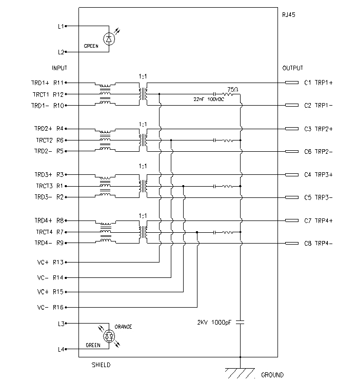
3.2.
Transmitter filter & Receiver filter 80~100 MHz –10dB MIN. load 100Ω
3.3 Common Mode Rejection
3.4 Cross Talk 3.5 INDUCTANCE @ 100KHz, 0.1V, 8mA DC BIAS Input(R11-R10), Input(R4-R5), Input(R3-R2), Input(R8-R9): 350mH MIN. ( @ 100KHz, 0.1V, 8mA DC BIAS) Input(R11-R10), Input(R4-R5), Input(R3-R2), Input(R8-R9): 350mH MIN. ( @ 100KHz, 0.1V, 24mA DC BIAS)
3.6 HiPot TEST
3.7 Balanced DC line current 720mA MAX @57VDC continuous 1.2A MAX @57VDC for 200milliseconds
SM000653 Vertical 10 Base-T w/o LED Vertical 100 Base-T w/o LED 1. MECHANIC DIMENSIONS 1.1. Dimensions

1.2. PCB Layout 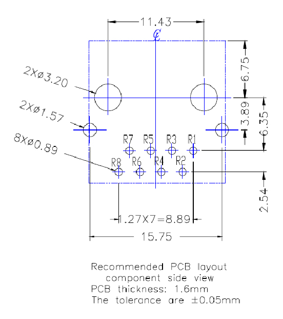
1.3. RJ PLUG SPECIFICATION  2. REQUIREMENTS
2.1 Design and Construction
2.2 Materials 2.2.1 Terminal Parts :
2.2.1.1
RJ Terminal : Phosphor Bronze ,
Thickness=0.30mm
2.2.1.2
Input Terminal : Brass ,
Thickness=0.35mm
2.2.1.3
Link Terminal : Brass , Thickness=0.30mm
2.2.2 Plastic Parts :
2.2.2.1
Housing : High temp. Thermoplastic, Black
2.2.2.2
Case : High temp. Thermoplastic, Black
2.2.2.3
Spacer : High temp.
Thermoplastic, Black
2.2.3 Shell Parts :
2.2.3.1
Shell : Stainless, Thickness=0.20mm
2.3 Operating and Storage Temperature 2.3.1 Operating Temperature : -40℃ TO +85℃ 2.3.2 Storage Temperature : -40℃ TO +85℃
2.4 RJ45 specifications: 2.4.1 Insulation Resistance: 500MΩMin 2.4.2 Dielectric Withstanding Voltage: 1000VAC Min
3. ELECTRICAL CHARACTERISTICS 3.1. SCHEMATIC 
3.2.
Transmitter filter & Receiver filter
3.3 Common Mode Rejection
3.4 Cross Talk 3.5 INDUCTANCE @ 100KHz, 0.1V, 8mA DC BIAS Input(R1-R3), Input(R4-R6) : 350mH MIN.
3.6 HiPot TEST Input(R4-R6) to Output(C3-C6) : 1500VAC, 60sec or 2250VDC, 60sec 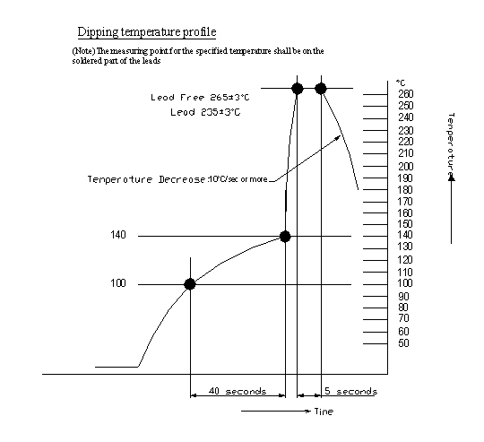 |
|
Copyright © 2008
Summit Magnetics Corp.
|
 with LED for PoE